Project Shopping List
Adding a subpanel in a detached garage is a project that transforms how you use the space – it powers lighting, outlets, tools, an EV charger, and refrigerators without running individual circuits to each from the main panel. A properly installed 60A or 100A subpanel in a garage handles every electrical need for most homeowners and involves significant but manageable electrical work. This is an advanced DIY project because it requires working at the main panel, running a long feeder cable, and grounding the subpanel correctly – all of which have safety implications if done incorrectly.
A permit and inspection are required. This is non-negotiable for subpanel installations – an uninspected subpanel with a wiring error is a house fire or electrocution waiting to happen. This guide provides the knowledge to do the work correctly and to understand the inspection requirements.
What You’ll Need
Tools
- Non-contact voltage tester and multimeter
- Drill and large bit set
- Conduit bender
- Wire stripper and cable cutter
- Screwdrivers and socket wrench set
- Trenching shovel or rented trencher (for underground feeder)
Materials
- Subpanel (60A or 100A, matching main panel brand preferred but not required)
- Feeder cable – 4/3 NM-B cable for 60A or SER 2/2/2/4 aluminum service entrance cable for 100A
- Or: conduit (PVC Schedule 40 or EMT) with THWN individual conductors
- Ground rods (two required by NEC) and clamps
- Two-pole breaker for main panel (60A or 100A)
- PVC conduit and fittings for underground run
Step 1: Determine the Subpanel Size and Feeder
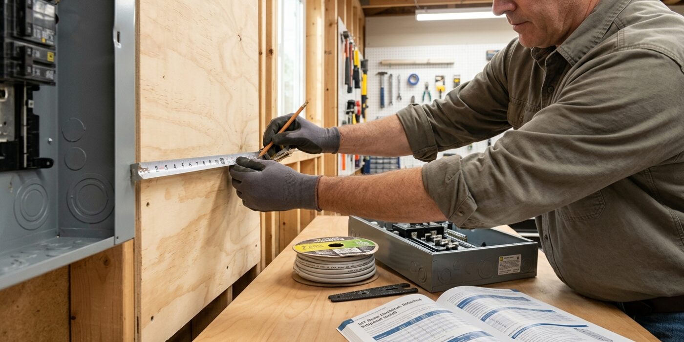
Choosing the right subpanel size is the most critical planning step for your garage project. Think of your subpanel as a small branch off your home’s main electrical system. A 60A panel is perfect for standard needs, like running a few power tools, LED lighting, and an EV charger. If you plan on running a professional woodshop with heavy machinery, space heaters, or air conditioning simultaneously, opt for a 100A panel to avoid tripping breakers.
You must also select the correct feeder wire, which brings power from your main house panel to the garage. Your wire size is dictated by your chosen amperage: use 4 AWG copper or 2 AWG aluminum for 60A, and 2 AWG copper or 1/0 AWG aluminum for 100A. Since aluminum is significantly more affordable for the long underground run to your garage, it is the industry standard for this task. Just remember: whenever you use aluminum wire, you must apply a generous coating of anti-oxidant joint compound to the ends. This prevents corrosion and ensures a safe, reliable connection.
Beginner Tip: Never guess on your wire size. If you are unsure about the distance between your house and garage, check with your local building department. Voltage drop occurs over long distances, and you may need to increase your wire gauge size if your garage is more than 100 feet away from the main panel.
Pro Tip: Buy your anti-oxidant compound in a small squeeze tube rather than a tub. It is much easier to apply precisely to the wire strands without getting the sticky, grey residue all over your hands or your new electrical panel.
Step 2: Plan and Permit the Installation
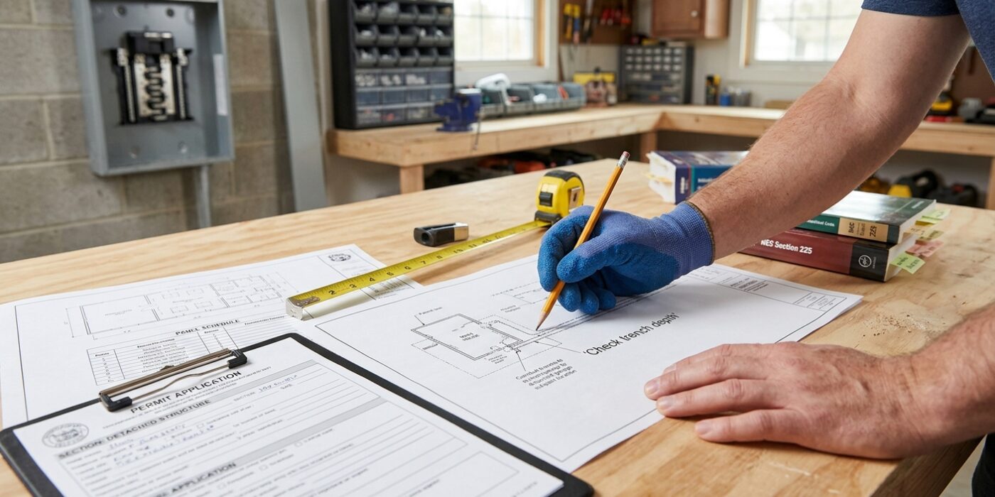
Before you lift a single tool, you must create a clear roadmap for your electrical project. Start by drawing a simple floor plan that identifies your home’s main service panel and the exact path the power lines will travel to your garage. You need to calculate the precise distance of the “feeder run,” as this determines the thickness of the wire (gauge) required to prevent voltage drop. Specify that your underground conduit must be buried at least 18 to 24 inches deep – depending on local code – using rigid PVC conduit to protect the wires from moisture and physical damage.
Once your diagram is complete, take it to your local building department to file for a permit. This step is non-negotiable; inspectors aren’t there to judge your work, but to ensure your system is safe from fire hazards. They will check that your grounding system is independent and that your wire sizing matches your intended amperage.
Beginner Tip: Never buy your materials before your permit is approved. Local codes often have specific requirements for conduit type or wire insulation ratings, and buying the wrong gear early is a costly mistake.
Pro Tip: When planning your route, choose the path of least resistance. Avoid sharp 90-degree bends whenever possible; instead, use two 45-degree elbows. This significantly reduces friction, making it much easier to pull the heavy electrical cables through the conduit later.
Step 3: Trench the Feeder Route
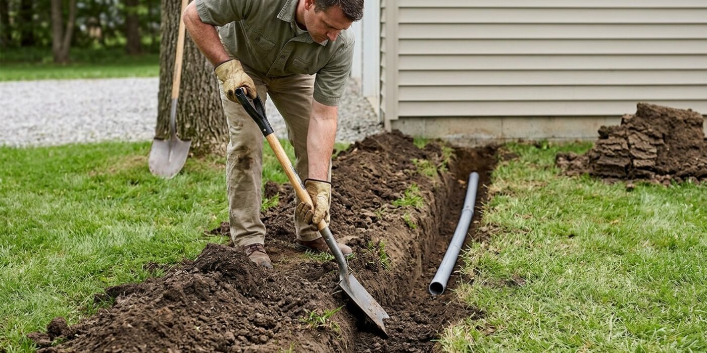
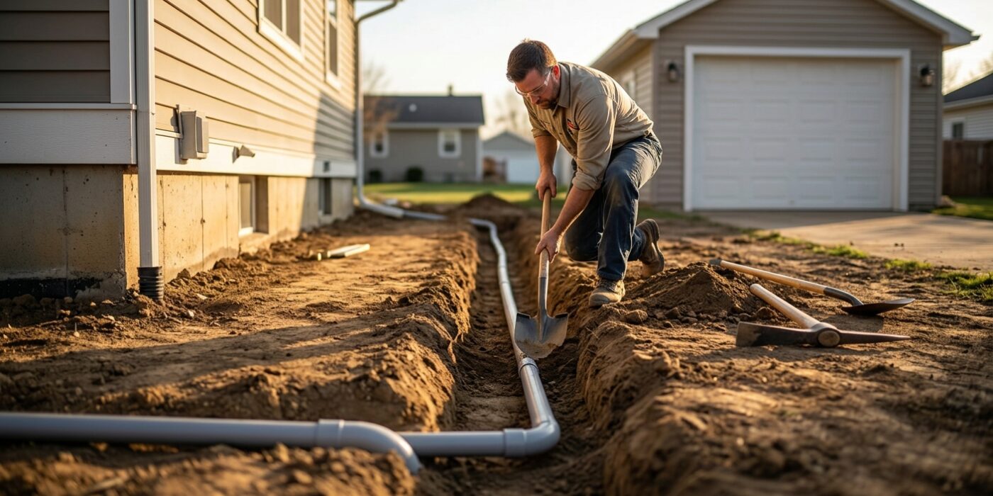
Now it is time to connect your buildings by digging a trench. Because you are working with electricity, safety is the priority. You need to bury your conduit at least 18 inches deep in soil, or 12 inches if you are digging underneath a concrete path. This depth protects the wires from garden shovels or accidental damage.
Use Schedule 40 or 80 PVC conduit for the path. When you reach the house and garage, use a “sweep” elbow – a gentle, long curve – rather than a sharp 90-degree corner. If the bend is too tight, the heavy feeder wires will get stuck when you try to pull them through later. Ensure your conduit stubs extend at least a foot above the ground at both entry points so you have plenty of room to work with once you reach your electrical boxes.
Beginner Tip: Before you break ground, call 811 or your local utility marking service. They will come out for free to mark any existing gas, water, or internet lines hidden in your yard. Digging into an unmarked utility line is dangerous and very expensive to fix.
Pro Tip: To make the job noticeably easier, use a “trenching shovel.” These have a long, narrow blade designed specifically for cutting through tight soil and roots. If you are digging a long distance, renting a powered walk-behind trencher from your local tool shop will save you hours of back-breaking labor.
Step 4: Pull the Feeder Conductors
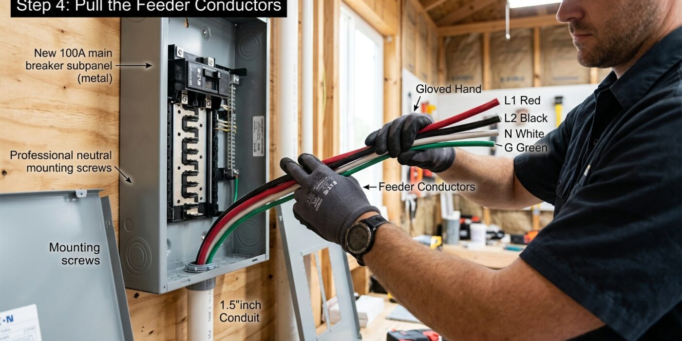
Now that your conduit is installed, it is time to feed your electrical wires – known as conductors – from your main house panel to the new subpanel in your garage. Before you start, coat the entire length of your wires generously with wire-pulling lubricant (cable lube). This reduces friction, preventing the insulation from snagging or tearing as the wires travel through bends.
You must pull all conductors at the same time so they glide through the conduit as a single bundle. For a 60A feeder, use two 4 AWG hots, one 6 AWG ground, and one 4 AWG neutral. For a 100A feeder, use two 2 AWG hots, one 4 AWG ground, and one 2 AWG neutral. Because this is a detached structure, the National Electrical Code (NEC) requires you to keep the neutral and ground buses completely separate in the subpanel; they should never touch or share a connection point.
Beginner Tip: Never pull wires by tugging on individual strands or the plastic insulation, as this can stretch or damage the copper. Always secure your bundle together with electrical tape wrapped tightly in a tapered “pulling head” shape so the bundle moves smoothly without catching on conduit joints.
Pro Tip: If the pull feels difficult, stop immediately. Attempting to force a stubborn wire through a pipe often leads to damaged insulation. Instead, enlist a partner to feed the wire into the conduit from the house end while you pull from the garage side. Keeping the wire straight and free of kinks before it enters the pipe makes the entire process significantly easier.
Step 5: Install the Subpanel and Ground Rods
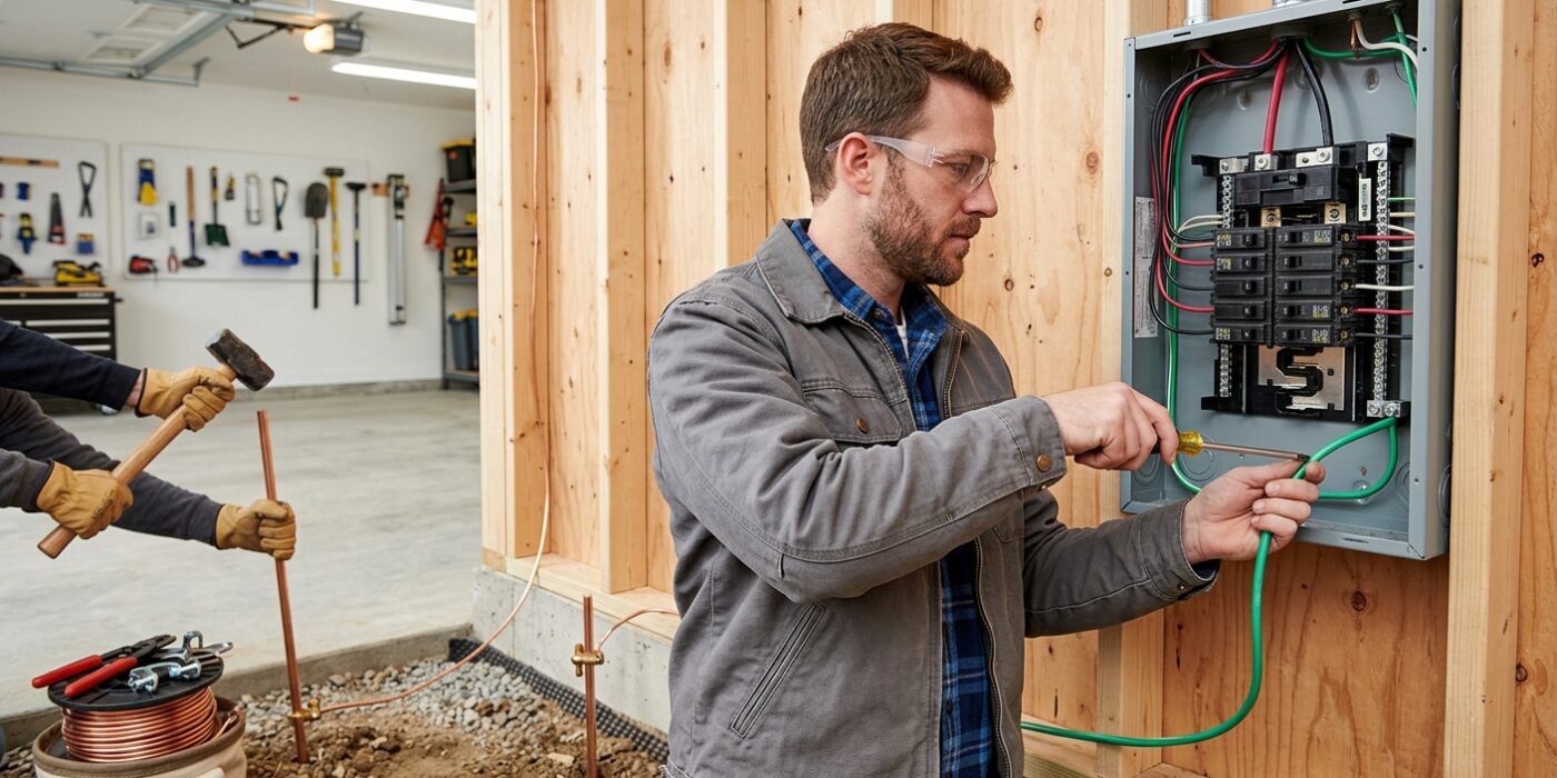
Now it is time to secure your hardware. First, mount your subpanel to the garage wall studs using appropriate wood screws. Ensure it is level so your breakers sit straight. Next, drive two 8-foot copper-clad ground rods into the earth at least 6 feet apart near your garage foundation. These rods provide a safe path for electrical surges to enter the ground.
You must connect these rods using 6 AWG bare copper wire, secured with approved ground clamps. Run a continuous length of this same wire from your subpanel’s ground bus to the rod system. Critically, because this is a detached structure, you must isolate the neutral and ground. Locate the green bonding screw inside the panel that connects the neutral bar to the metal enclosure and remove it entirely. This keeps your electricity running safely and prevents the metal box from becoming energized.
Beginner Tip: Ensure the top of your ground rods are flush with the ground or buried a few inches deep to avoid tripping hazards or damaging them with a lawnmower. Never leave them sticking up as a sharp obstacle.
Pro Tip: Driving ground rods through rocky soil can be exhausting. Use a rotary hammer drill with a ground rod driving attachment if you have access to one. If you are doing this by hand, try using a deep-well socket over the end of the rod to keep your sledgehammer from mushrooming the top of the metal.
Step 6: Connect at the Subpanel and Main Panel
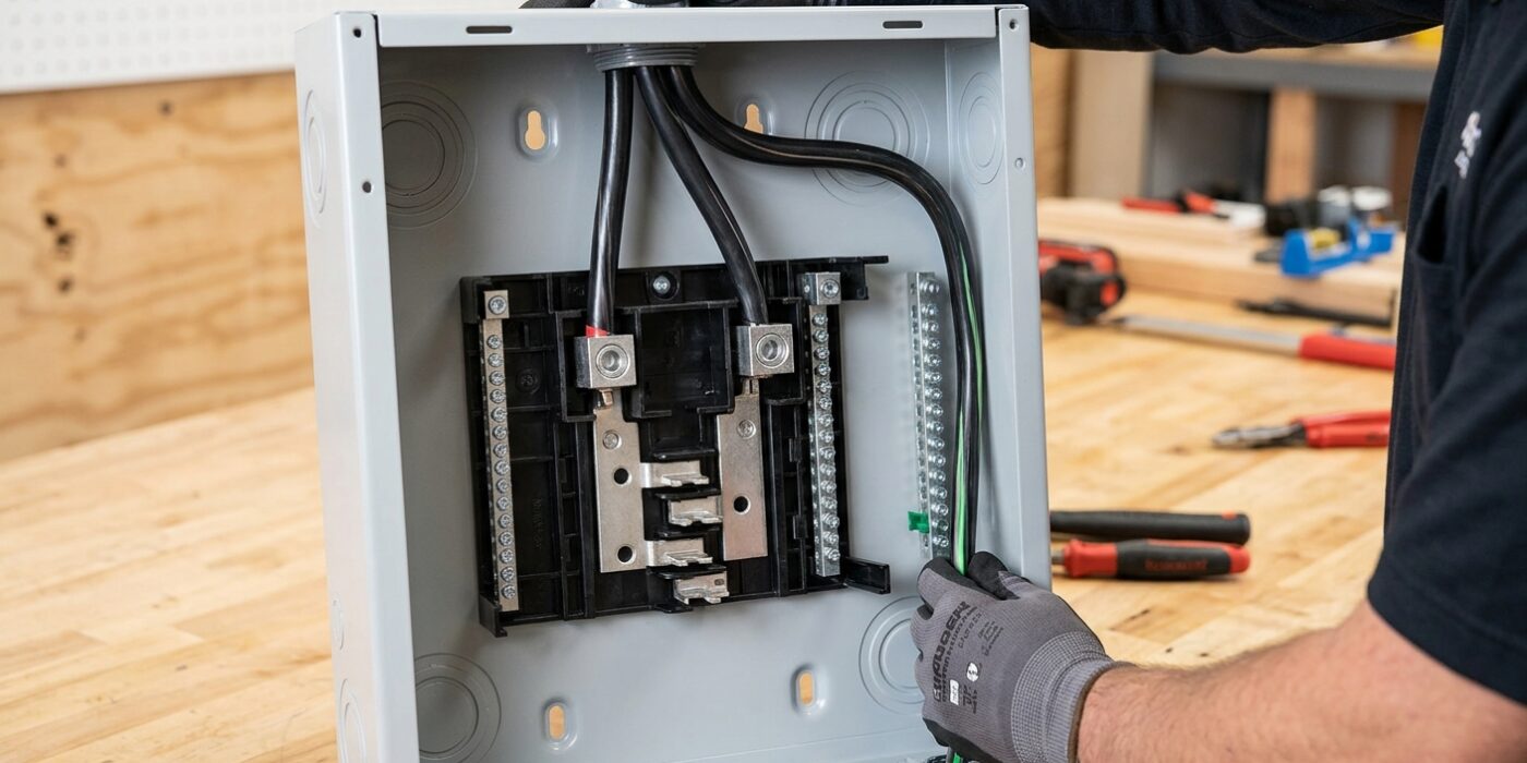
Now that your feeder conduit is run and the wires are pulled, it is time to make the connections. First, ensure the main power to your home is off at the main service panel. Strip about 3/4 inch of insulation from the ends of your feeder wires using a wire stripper. At the subpanel, insert your two hot (usually black/red) wires into the large main lugs at the top and tighten them firmly with a screwdriver; you want them snug enough that the wire doesn’t budge. Connect the white neutral wire to the neutral bus bar and the bare or green ground wire to the ground bus bar.
Beginner Tip: The most critical mistake to avoid is failing to remove the bonding screw or jumper strap in your subpanel. In a detached garage, the neutral and ground wires must remain completely separate. If your subpanel came with a small green screw installed that connects the neutral bus to the metal panel enclosure, back it out and set it aside. Failing to do this is the number one reason subpanel installations fail electrical inspections.
Pro Tip: Before inserting aluminum wires into the lugs, coat the stripped ends with a thin layer of anti-oxidant joint compound, often called Noalox. This prevents oxidation from forming between the aluminum wire and the copper/steel lug, which ensures a reliable, heat-free connection that will last for decades. Once tightened, give each wire a firm tug to ensure it is securely held in the terminal.