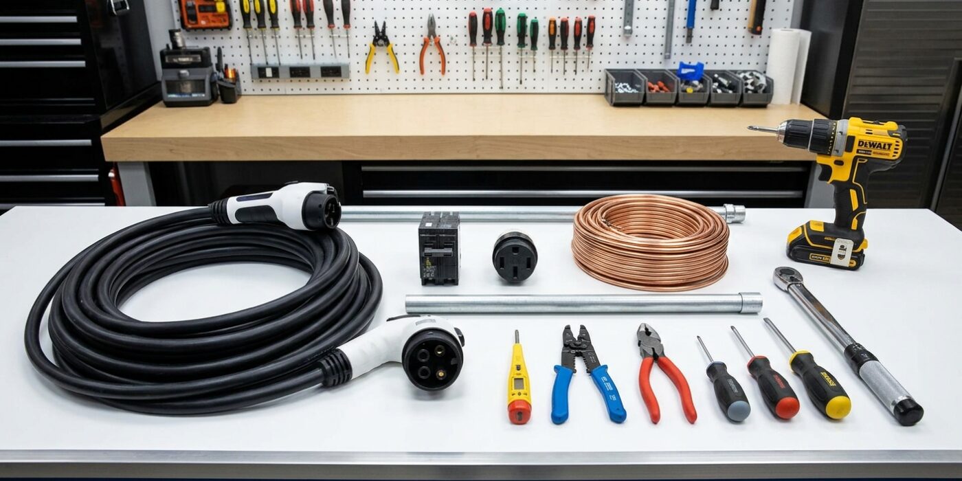
Project Shopping List
Installing a Level 2 EV charger at home is one of the most practical electrical projects for electric vehicle owners – it reduces overnight charge time from 30+ hours (Level 1, standard 120V outlet) to 4–8 hours. Level 2 chargers operate on 240V and require a dedicated circuit, which means either an available 240V breaker slot in your panel or a subpanel in your garage. This is a legitimate intermediate electrical project, though the final connection to the panel and the permit inspection are required in most jurisdictions.
This guide covers planning the circuit, running the wire, and mounting the EVSE (electric vehicle supply equipment). Permit and inspection are mentioned because they’re legally required and protect your EV and insurance – don’t skip them.
What You’ll Need
Tools
- Non-contact voltage tester
- Drill and bits
- Conduit bender (if using rigid conduit)
- Fish tape
- Wire stripper
- Screwdrivers
- Level
Materials
- Level 2 EVSE (hardwired unit, 48A rated for most setups) – ChargePoint Home Flex, Emporia, or Wallbox are common
- 6/3 NM-B cable or THWN wire in conduit (for 50A circuit)
- 50A 2-pole circuit breaker
- Conduit (EMT or PVC) and connectors if not running cable in wall
- Weatherproof electrical box (for outdoor garage installations)
Step 1: Calculate the Required Circuit Size
Before you purchase any equipment, you must determine how much power your charger requires and if your home’s electrical panel can safely handle the extra demand. Think of your electrical panel like a water pipe; you need to ensure there is enough flow capacity before adding another faucet.
Most Level 2 chargers draw between 30 and 48 amps. Because these chargers run for long periods, the National Electrical Code (NEC) requires a safety buffer called a “continuous load” rating, which is 125% of the charger’s output. For example, a 40-amp charger needs a 50-amp circuit (40 x 1.25 = 50). Many chargers are adjustable, meaning you can lower the settings to match the capacity you have available. Check your main panel’s label – usually found on the inside of the door – to see your total amperage. If you are near your limit, you may need a professional load calculation to ensure you won’t trip your main breaker.
Beginner Tip: Never assume your panel has “extra room” just because there is an empty slot. An empty physical slot does not always mean you have the electrical capacity to support a high-draw appliance like a charger without upgrading your service.
Pro Tip: Look for a charger with “smart” features or internal software settings. By choosing a unit that allows you to dial down the amperage via a mobile app or physical dip-switch, you can install a powerful charger today that safely fits your current panel limits, then upgrade to full speed later if you ever upgrade your electrical service.
Step 2: Obtain Permits
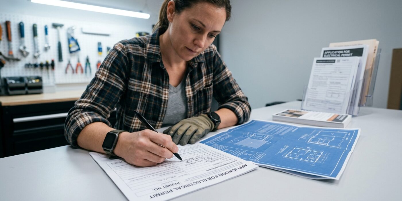
Before you touch a single wire, you must head to your local city or county building department’s website. Installing a Level 2 charger involves connecting high-voltage equipment to your home’s electrical panel, which carries significant safety risks. Obtaining an electrical permit ensures that a certified inspector will verify your work, protecting your home from fire hazards and ensuring your insurance policy remains valid. When you apply, you will likely need to provide a site plan, which is just a simple sketch showing where your charger will be mounted in relation to your electrical panel and your vehicle’s parking spot.
Beginner Tip: Do not skip the permit process thinking you can fly under the radar. If you ever decide to sell your home, an unpermitted electrical installation will almost certainly appear during the home inspection, forcing you to pay for expensive retroactive permits and potentially professional corrections before the sale can close.
Pro Tip: Before filling out your permit application, call your local electric utility company and ask if they offer “EV charger rebates.” Many utilities provide significant cash back for installing a charger, but they almost always require proof of a closed, approved permit and a copy of the final inspection report. Having these documents organized from the very beginning makes collecting that extra cash later much smoother.
Checking these boxes now keeps your project legal, safe, and potentially more affordable. Once the city gives you the green light, you can move forward with confidence knowing that your setup meets all safety codes.
Step 3: Run the Circuit Cable
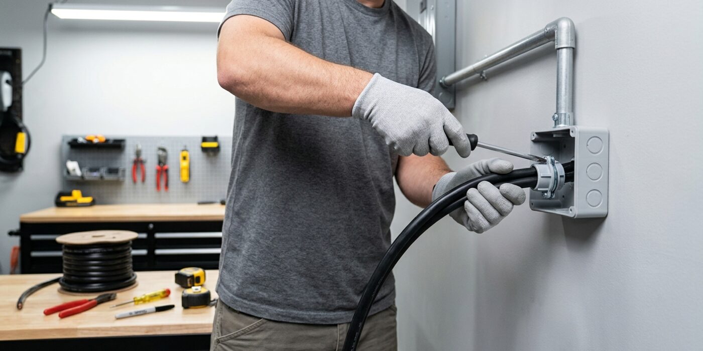
Now that your path is clear, it is time to route your heavy-duty cable from the main electrical panel to your charger’s mounting location. Because this cable carries high voltage, it must be protected from physical damage. If you are running the wire through a garage or basement where it will be exposed, you must use conduit – sturdy plastic or metal piping – to house the wires. Secure this conduit to the wall studs using pipe straps every 3 to 4 feet to prevent sagging.
For a 50A charger, use 6 AWG copper wire; for a 40A charger, use 8 AWG. If your run exceeds 50 feet, always choose the thicker wire size to prevent “voltage drop,” which ensures your car charges efficiently. When feeding the wire through your conduit or wall cavities, move slowly to avoid kinking the thick, stiff copper strands. Ensure you leave at least 6 to 12 inches of extra wire dangling at both the panel and the charger end to give yourself plenty of room to make your final connections later.
Beginner Tip: Avoid pulling the wire with excessive force. If the cable feels stuck inside the conduit, do not yank it. Simply pull it back a few inches and try again with a gentle, steady motion. If you have a helper, have them guide the wire into the opening while you pull to prevent snags.
Pro Tip: Use a non-conductive wire-pulling lubricant (often called “wire lube”) on the cable before pushing it through long, tight sections of conduit. This drastically reduces friction and makes the cable slide through bends as if it were greased lightning.
Step 4: Mount the EVSE
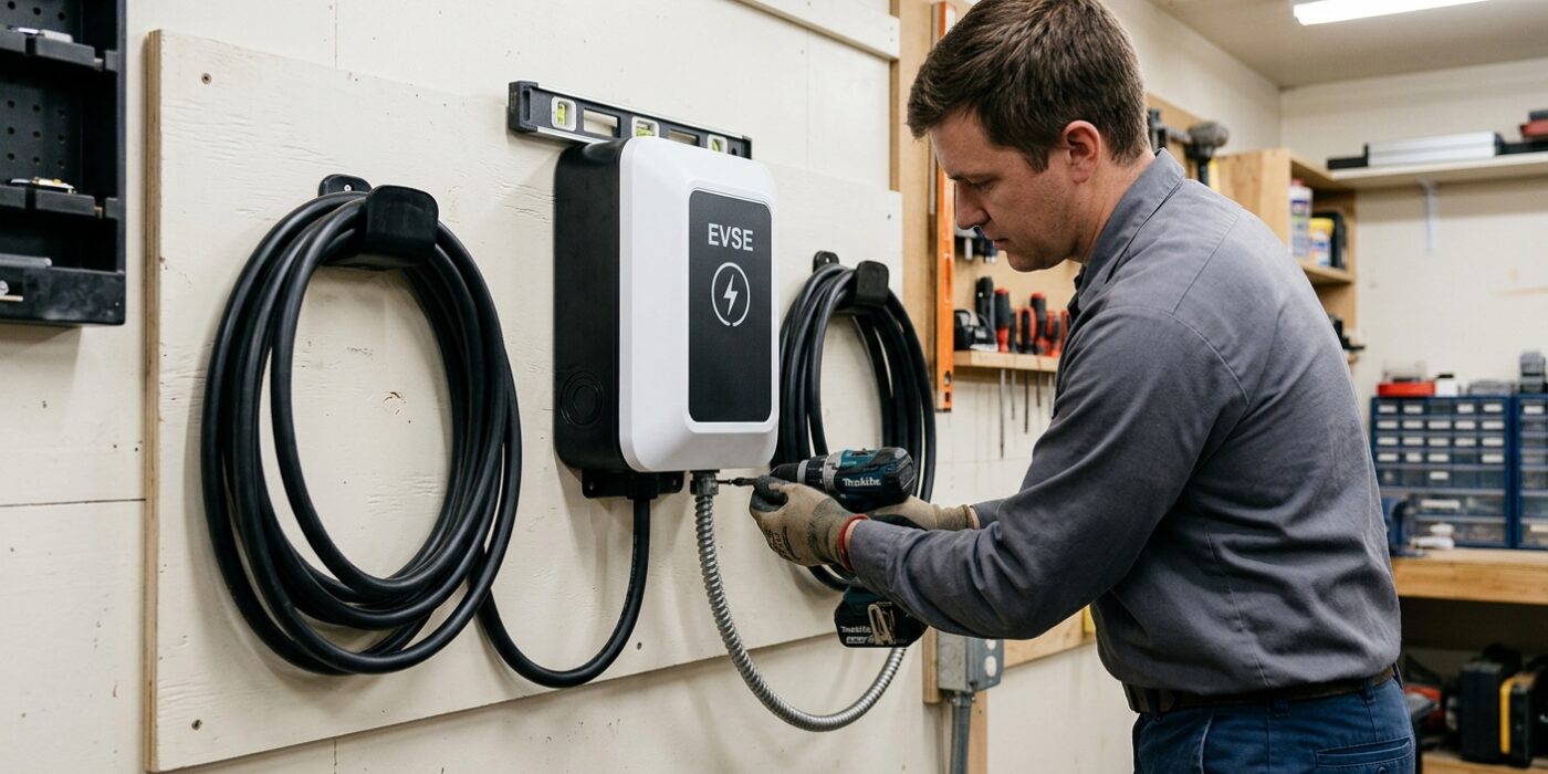
Now that your wall is clear, it is time to secure your EVSE (the charger unit) to the wall. This unit is the heart of your setup, so proper placement is vital for both safety and convenience. Start by finding the mounting template included in your charger’s box. Position this template on the wall, typically with the center point at 48 inches from the floor, as this height keeps the heavy cable from dragging on the ground and prevents it from being a tripping hazard.
Use a level to ensure the template is perfectly straight before marking your drill holes. Once marked, drill pilot holes and secure the bracket or unit using the hardware provided by the manufacturer. After the unit is mounted, gently feed your supply cable through the hole – or “knockout” – at the bottom of the unit. Ensure the cable has enough slack to be easily wired inside, but not so much that it creates a tangled mess behind the housing.
Beginner Tip: The most common mistake is drilling into a wall stud without checking for hidden pipes or wires first. Always use a stud finder to locate the wood framing behind your drywall, and double-check that you aren’t drilling near existing electrical outlets or light switches where house wiring might be running vertically inside the wall.
Pro Tip: If your garage wall has a rough texture or is made of concrete, use a small piece of blue painter’s tape over the spot where you intend to drill. This prevents your drill bit from “skating” or sliding across the surface, helping you start your holes exactly where you marked them.
Step 5: Wire the EVSE
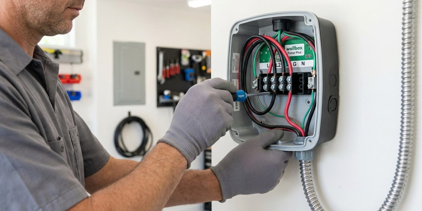
Now it is time to connect your charger to the electrical wires. Before beginning, double-check that your circuit breaker is still in the “off” position. To start, strip about 3/4-inch of the plastic insulation off the end of each wire using your wire strippers. Inside the EVSE unit, you will find a terminal block with clearly labeled slots. Insert the black wire into the L1 terminal and the red wire into the L2 terminal. If your specific unit includes a white wire, connect it to the neutral terminal. Finally, secure the bare copper or green ground wire to the grounding lug, which is usually marked with a green screw or a ground symbol. Use a screwdriver to tighten each terminal screw firmly; give each wire a gentle tug afterward to ensure it is locked in place. This connection must be tight to prevent heat buildup, which can occur if electricity faces resistance from a loose wire.
Beginner Tip: A very common mistake is leaving too much bare copper wire exposed outside the terminal block. Ensure that only the insulated portion of the wire is visible near the entry point; if you see bare metal sticking out, it could cause a short circuit. Trim the excess back if necessary before tightening.
Pro Tip: Use a torque screwdriver if you have one. Manufacturers often specify a exact pound-inch rating in the manual. Even without one, once the screw stops turning easily, give it an extra quarter-turn to ensure a solid, permanent connection that won’t vibrate loose over time.
Step 6: Panel Connection and Inspection
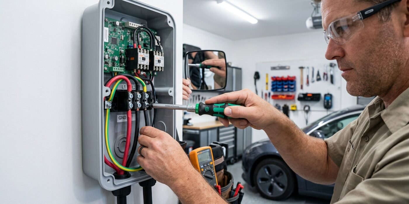
Now that your wiring is routed to the panel, it is time to make the final connections. First, ensure the main power to your home is completely shut off. Because you are installing a 240V circuit, you will be using a 2-pole breaker, which effectively takes up two slots in your electrical panel. Strip about 3/4 of an inch of insulation from the ends of your black and red wires, then insert them firmly into the terminals on the new breaker and tighten the screws until they are snug and the wire does not pull out. Connect your white wire to the neutral bus bar and the bare copper wire to the ground bus bar inside the panel. Double-check that all connections are tight, as loose wires can create heat and are a common fire hazard.
Beginner Tip: A common mistake is leaving the wires too long or messy inside the panel. Try to route your wires neatly along the outer edges of the panel cabinet before bringing them to the breaker. This keeps the interior clear, allows for better airflow, and makes it much easier to identify wires during future maintenance or inspections.
Pro Tip: Before you snap that new breaker into place, take a photo of the panel label and your wiring. Having a clear reference picture is incredibly helpful when you meet with your local inspector, as they will want to see exactly how the circuit is landed and labeled before signing off on your permit.