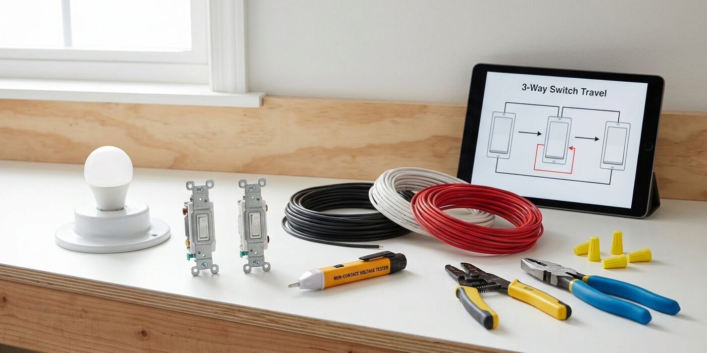
Project Shopping List
A three-way switch circuit controls one light from two different locations – at the top and bottom of stairs, at each end of a long hallway, or at two entry points to a large room. Wiring three-way switches is one of the first electrical jobs that trips up otherwise capable DIYers because there are multiple wiring configurations and the color coding of the wires doesn’t always follow intuitive convention. This guide demystifies the wiring with a clear explanation of how three-way switches work, then gives you the step-by-step installation.
You’ll need to work at both switch boxes in sequence. The critical skill is photographing and labeling the existing wiring before disconnecting anything – the photo is your reference for the new connection.
What You’ll Need
Tools
- Non-contact voltage tester
- Phillips and flathead screwdrivers
- Wire stripper
- Needle-nose pliers
- Continuity tester or multimeter (helpful for identifying common terminal)
Materials
- Two three-way switches (must be three-way – four terminals: black common, two brass traveler screws, and green ground)
- Wire nuts
- Electrical tape
- Masking tape and marker for labeling wires
Step 1: Understand How Three-Way Switches Work
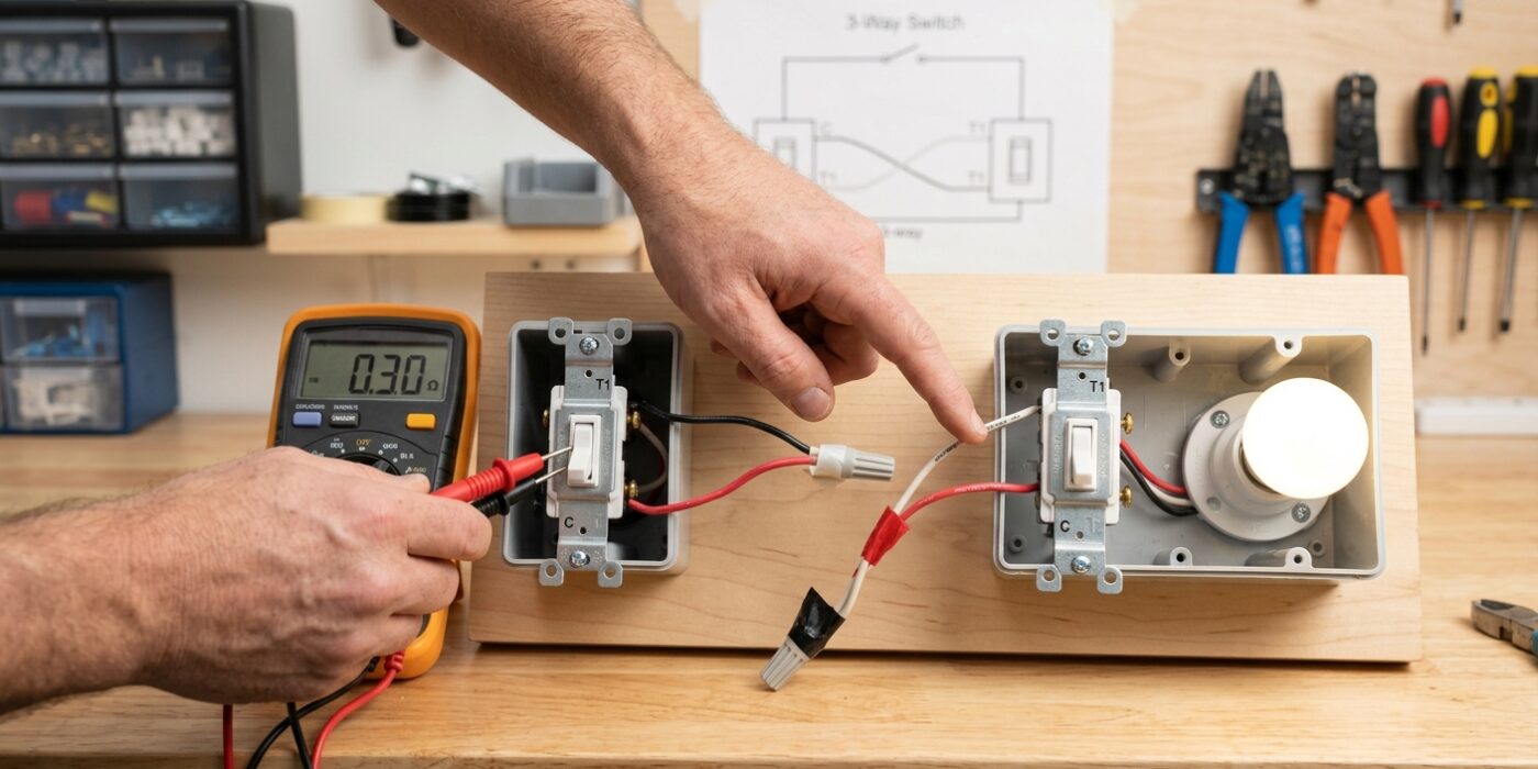
Before you touch a screwdriver, it is vital to understand the “logic” behind these switches. Unlike a standard single-pole switch that simply acts as a bridge, a three-way switch acts like a railroad track switcher. It has one common terminal (marked with a black or dark-colored screw) and two traveler terminals (brass-colored screws).
The common terminal is the main gateway: at the first switch, it connects to your power source; at the second switch, it leads directly to the light. The two traveler wires connect the brass screws of both switches together. When you flip a switch, you are toggling which path the electricity takes through those traveler wires. Because the switches work in tandem, flipping either one completes or breaks the circuit, allowing you to turn a single light on or off from two different points in the room.
Beginner Tip: The most common mistake is confusing the common screw with the traveler screws. Before you remove any wires from your old switches, look for the screw that is a different color than the others. Use a piece of masking tape to label the wire attached to that specific screw as “Common” before disconnecting anything.
Pro Tip: Take a high-resolution photo of your current wiring configuration before disconnecting a single wire. Having a visual reference of exactly which wire color goes to which screw terminal is a lifesaver if you get interrupted or second-guess yourself midway through the project.
Step 2: Shut Off Power and Photograph Both Boxes
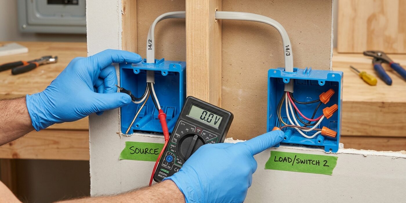
Before you even touch a screwdriver, your first priority is safety. Locate your home’s electrical panel and flip the circuit breaker corresponding to the room you are working in. Since 3-way switches involve two different boxes, power could be coming from either direction. Use a non-contact voltage tester – a pen-shaped tool that beeps or glows near live wires – to verify that both switch boxes are completely dead. Gently wave the tip of the tester near every wire inside the boxes to be 100% sure.
Once you’ve confirmed the power is off, unscrew the switches from the wall and gently pull them out, leaving the wires attached. Take several high-resolution photos from at least three different angles, including close-ups of where each wire connects to the switch terminals. Use a piece of masking tape to label every single wire based on the terminal it was attached to (Common, Traveler 1, Traveler 2, and Ground). This step is your roadmap; if you get confused later, these photos will be the difference between a quick finish and a frustrating afternoon.
Beginner Tip: Never assume the color of the wire indicates its function. Just because a wire is black or red doesn’t mean it’s a “traveler.” Always label based on the screw terminal it was connected to, not the wire color itself.
Pro Tip: Place a piece of painters tape over the main breaker in your electrical panel with a note that says “Working on switches – do not turn on.” This prevents a well-meaning family member from accidentally flipping the power back on while your wires are exposed.
Step 3: Identify the Wires in Each Box
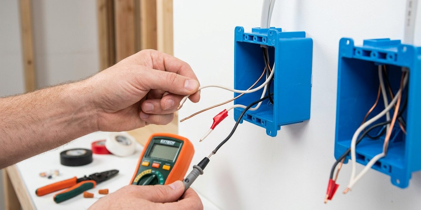
Before you connect any wires, you must identify exactly which wire is which. Think of your switch boxes as a puzzle; knowing the role of each wire is the key to solving it. Gently pull the wires out from each box so you can see them clearly. You should see a bundle of wires emerging from the wall. In Switch Box 1, look for the incoming power cable and the 3-wire cable heading to the second box. In Switch Box 2, you will find that same 3-wire cable and the wire leading directly to your light fixture.
Use your non-contact voltage tester on every wire to confirm the power is truly off. Once safe, use small pieces of masking tape to label each wire based on your earlier photographs. If a wire is meant to be hot but is white, wrap a small band of black electrical tape around the end; this is a safety standard that tells anyone opening the box in the future that this wire is carrying current, not neutral.
Beginner Tip: A common mistake is assuming wire colors are universal. Never rely on color alone! Older homes often have non-standard wiring colors. Always trust your labels and the photographs you took during the demolition phase over the color of the insulation.
Pro Tip: To keep your wires organized and prevent them from retracting back into the wall, gently bend the ends of the wires into a slight hook shape after labeling them. This holds them securely at the front of the box while you prepare your connections.
Step 4: Connect Switch 1
Now it is time to bring your first switch to life. Start by taking your black hot wire coming from the power source and attaching it to the black “common” screw on the switch; ensure about 3/4 inch of insulation is stripped back so the copper sits securely under the screw head. Next, connect your two traveler wires – usually red and black – to the two brass-colored screws. Because these travelers work in tandem, you do not need to worry about which goes to which brass screw; both will function perfectly. Finally, attach your bare copper or green ground wire to the green grounding screw at the base of the device. Gently fold the wires in an accordion-style pattern to help them slide easily into the back of the electrical box before screwing the switch flush against the wall.
Beginner Tip: A common mistake is leaving too much bare wire exposed. If more than 1/4 inch of copper extends beyond the screw head, you create a risk of a short circuit. Use your wire strippers to measure precisely, and remember that you can always trim a little more off if the exposed section is too long.
Pro Tip: When tightening the screws, loop your wire in a clockwise direction around the terminal. As you tighten the screw, the rotation will naturally pull the wire tighter into the screw shank, creating a much stronger, more reliable connection that won’t wiggle loose over time.
Step 5: Connect Switch 2
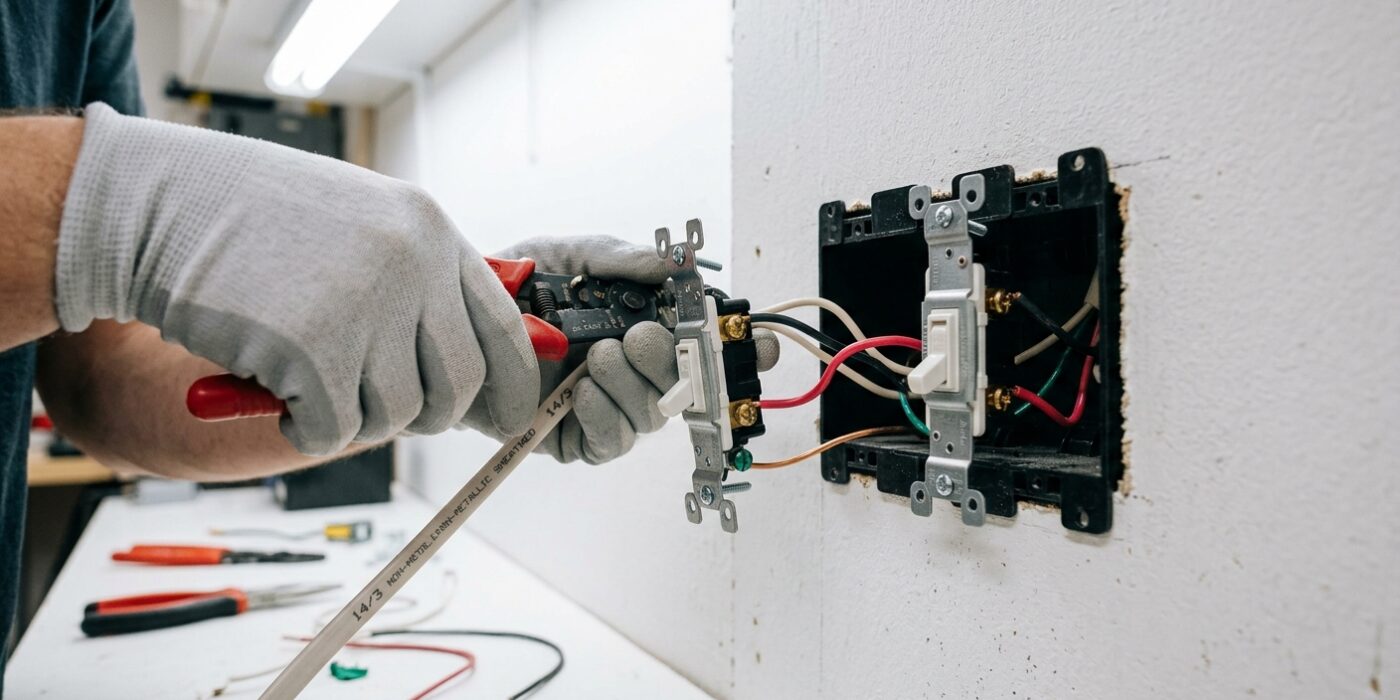
Now it is time to finish your wiring at the second switch location. You will be working with three types of connections: the two traveler wires, the load wire (which heads to the light fixture), and the ground wire. First, take your two traveler wires – usually red and black – and attach them to the two brass-colored screws on your new switch. It does not matter which traveler goes to which brass screw, so don’t worry about getting them swapped. Next, identify the common terminal, which is marked by a distinct black or dark-colored screw. Attach the wire leading to your light fixture here. Finally, connect your bare copper or green ground wire to the green screw at the bottom of the switch.
Beginner Tip: Ensure that no bare copper is exposed beyond the screw head. If you see more than a quarter-inch of bare wire sticking out after tightening, back the screw out, trim the excess with your wire cutters, and re-tighten. Exposed wire can accidentally touch the metal box and cause a short circuit.
Pro Tip: Before you fold the wires back into the electrical box, gently tug on each individual wire to confirm it is firmly seated under the screw plate. Then, accordion-fold the wires neatly behind the switch rather than shoving them in haphazardly. This keeps the box organized and prevents internal tension that could wiggle a connection loose over time.
Step 6: Restore Power and Test All Combinations
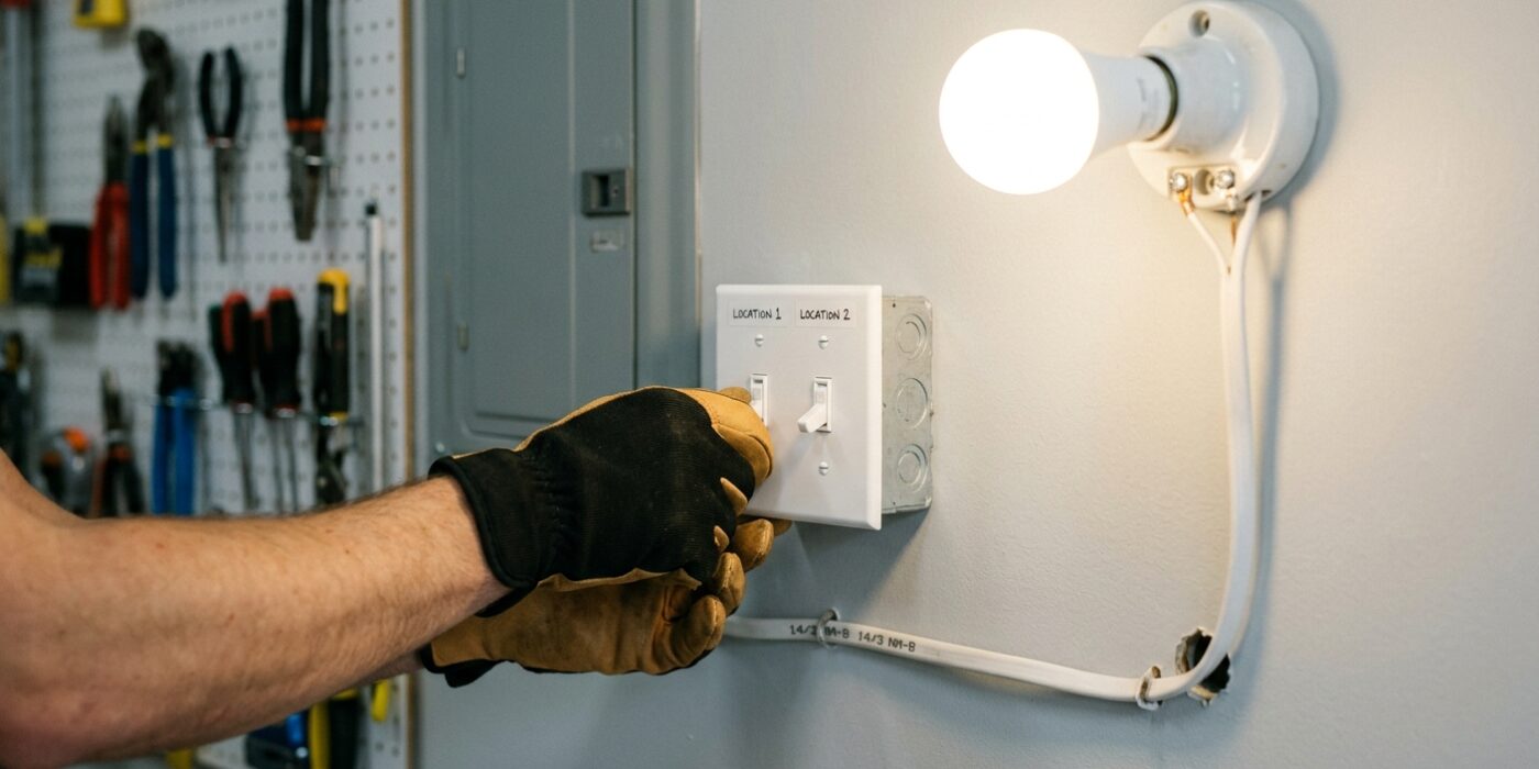
Now that your switches are securely mounted, it is time to bring the circuit back to life. Head to your electrical panel and flip the circuit breaker back to the “On” position. Return to your two switches and test every possible configuration: both up, both down, and the two mixed combinations. The light should toggle on or off whenever you move either switch. If you find the light responds only to one switch while the other does nothing, don’t worry – you haven’t broken anything. This simply means the “common” wire (usually black or marked with a dark screw) was accidentally swapped with one of the “traveler” wires (the brass-colored screws). Simply turn off the breaker again, open the switch box that isn’t performing, and move the wire currently on the common terminal to one of the brass terminals, then move the wire from that brass terminal over to the common.
Beginner Tip: Never force a switch into the wall box if it feels tight. If the wires are bunched up, gently push them into the back of the box and fold them like an accordion rather than stuffing them in a messy ball. This prevents wire insulation from being pinched or damaged, which could cause a dangerous short circuit.
Pro Tip: Before you close up the wall plates, use a small piece of masking tape to label the back of each cover plate with a “C” to mark where the common wire is located. This takes seconds now but will save you an immense amount of frustration if you ever need to replace a switch five years down the road.